Intelligent 1 Axis Stepper Motor Controller SP1. Modem option for long distance remote control.

1. New Speedy version SP1A available. Stepper motor axis rotation speed reaches 40Hz (40 revolutions/second with resolution of 0.225 deg for 1.8 deg/step stepper motor). 2. Supports continuous motion for constant rotation speed applications. 3. Supports 4 Axes simultaneous contouring by fast low level SP1A command. 4. Schematics (electrical circuit) is available. 5. Full package "Make it by yoursef" is also included.

Single Axis Stepper motor controller SP1 is a complete, serially controlled drive system for bipolar stepper motor. Using the intelligent microcomputer module SP1 allows host system (host computer) to concentrate on the task at hand while the SP1 performs all calculations and operation of stepper motor. Desired operating speed, acceleration/deceleration rate and drive modes can be configured once and then a single command (a string of ASCII characters) used as required, to move to relative position. Motion status can be tested by the controller commands during motion. It is indicated also by the top panel READY LED. Motor motion can be, in case of emergency, interrupted by pressing either one of the two buttons on the top panel or Right and Left limit switches. Position of the motor is maintained in a readable register, which can be read or set to zero by a simple command.

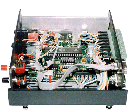
Inside SP1

Inside the controller. Click on picture to see electrical circuit.

Extra position control is obtained from implemented Quadrature encoder interface, which register is controlled by commands. User has option to enable/disable autonomous Stall/Motion detection, if external Quadrature encoder also is connected to SP1.

Standard configuration.

A built-in ramping function accelerates the stepper motor from a standstill to the desired speed over a specified time period, allowing faster final speed to be achieved, and also to decelerate the motor to give maximum load braking. Controller commands are obtained from host computer via serial port. The high-level commands simplify operation and incorporate into any programming language. They exhibit a comprehensive, easy to use instruction set. Serial interface is self-contained and connects to any computer or terminal. SP1 controllers are easily chained using standard RS-232 cables. Specific controller address (axis number, which has to be unique for each controller), is preprogrammed in nonvolatile (Flash) memory and becomes default.

Cascading the controllers into a chain.

Features

· High efficiency, low noise motor drivers. Bipolar motor PWM chopper type current control up to 1.5 A (AVE.) and 2.5 A (PEAK) per phase.
· 32 bits range : -2147483648 to 2147483647 steps per single motion.
· Smooth sinus wave micro stepping in 1/2 step, 1/4 step, 1/8 step gear modes.
· Speed 1…2000 micro steps/second (1...16000 for SP1A). Actual speed and resolution depends on gear factor.
· Manual or auto gearing modes. Auto gear mode combines both advantages - high resolution (1/8 step) and high speed. SP1 axis angular rotation frequency reaches 5 Hz (New! 40 Hz for speedy SP1A modification, which is based on Dallas DS89C440 or DS89C450 Ultra-High-Speed Flash Microcontroller) for 1.8 deg/step stepper motor.
· Supports a very slow motion. Time multiplier can reduce motion speed till 2000 times. Now supports continuous motion for precise constant speed applications.
· Open loop system with no position feedback required.
· Constant or Trapezoidal speed profile.
· Programmable maximum speed and acceleration rate.
· Nonvolatile flash memory for motion control variables, modem initialization instructions and default options.
· Home (Origin) and two limits inputs. Home position and limits detection, while moving.
· Simple, comprehensive manual controls with programmed resolution: front panel button manipulator plays joystick role.
· Large number of units can be chained and controlled from a single serial (RS-232) port.
· Modem option. Long distance remote control available through external Hayes-compatible type modem, hooked to serial input. User preprograms interface initialization protocol, which is saved in nonvolatile flash memory. Optional Phone Line Simulator SP2 should also be employed, if modem option to be used.
· Absolute position register (-2147483648 to 2147483647) in micro steps (1/8 of stepper motor step).
· Decodes Quadrature encoder signals for position detection. Absolute decode position register (32bits: -2147483648 to 2147483647) in encoder steps.
· Automatically supports stall (or motion) detection, if external Quadrature encoder is connected to SP1.
· Automatically reduces the motor power till 40% after motion is complete, minimizing heating while standby (holding) position.
· Comprehensive instruction set of 52 commands. Using the commands, even terminal (no host computer is necessary) can manage SP1 controller operation.
· Supports synchronous motion of several axes (stepper motors). Corresponding SP1 controllers must be chained to the same computer RS-232 port.
· Possibility to lock/unlock controller with password.
· Separate power input for stepper motor (+12…+36V) and board logic (+7…+9V).

Specifications

Motor compatibility Most types of stepper motors (5...12 volts), limited to 1.5 amps ( 2.5 A PEAK). Resistance per winding - less than 20 Ohm. For high speed applications low winding resistance and inductance is recommended
Case Plastic case, 160 mm x 60 mm x 140 mm (WxHxD)
Recommended Electrical supply for board Voltage +7...9V, current 300 mA 
Recommended Electrical supply for motor Voltage +24...36V, current 1...2A. Imax depends on motor coils inductance and current limiting resistors
Front panel facilities Mains board logic ON/OFF, Stepper motor power ON/OFF, Left and Right buttons manipulator, "Ready" LED
Rear panel facilities Phoenix Contact 16 pin connector (DFK-MC 1,5/16-GF-3,81 and MC 1,5/16-STF-3,81 types), Input 9 pin "D" connector, Output 9 pin "D" connector
Limits switching Facility for two mechanical limits and one home (origin) positioning switches
Signal Inputs Left limit, right limit, home position switches, Quadrature encoder A and B phase TTL level signals
Outputs +5V for Quadrature encoder, encoder ground. Phase A1, phase A2, phase B1, phase B2 for stepper motor
Recommended Cabling options 3 meter RS-232 standard lead with 9 pin serial port on PC, or special RS-232 twisted pair shielded cable for 3...15m communication. 1...3 meter 4 wire power cable for stepper motor
Modem option for a very long range communication Internal or external modem for computer, Phone line simulator SP2, external Hayes-compatible type modem, hooked to SP1 controller serial inputs, DB9-DB9 or DB9-DB25 adapter for modem, if necessary
Driver Driver provides current of 1.5 amps per phase at 36 volts. 1 micro-step of driver  = 1/8 of stepper motor step
Serial port default options 9600 baud rate, 8 data bits, No parity, 1 stop bit, No flow control. Baud rate can be changed to 4800, 19200, 28800, 57600, 115200
Temperature and humidity Standard moisture and temperature conditions for inside (room or laboratory) use
Programming platform No platform dependent. No need for special device driver. Even the terminal can manipulate the SP1 controller through RS-232 cable, using ASCII string commands. Easy communication with most terminal programs, C++, Basic and standard LabView software


Back Panel Phoenix Connector configuration.

Cabling to computer. Connector pins shown in the table below.

  RS-232 Pin Assignments (DB9 PC signal set for IN and OUT)
Pin 1 Received Line Signal Detector (Data Carrier Detect)
Pin 2 Received Data
Pin 3 Transmit Data
Pin 4 Data Terminal Ready
Pin 5 Signal Ground
Pin 6 Data Set Ready
Pin 7 Request To Send
Pin 8 Clear To Send
Pin 9 Ring Indicator


Standard RS-232 cable can be used for 1-3 meters range. Long communication distance needs twisted pair shielded cable.

DB9 - DB9 RS-232 twisted pair shielded cable for 5....15 meters range communication.